My Land Rover Defender

My Land Rover Defender
200Tdi 110

The rear on my vehicle

The rear on my vehicle
Not bad for 16yrs old

The rear seats

The rear seats
Re-upholstered by myself

Discovery 2 Seats

Discovery 2 Seats
Really comfortable

Part 2 The rear A Frame

Friday, May 27, 2011

Part two
First of all if you have the service manual, read it to see how it comes apart.

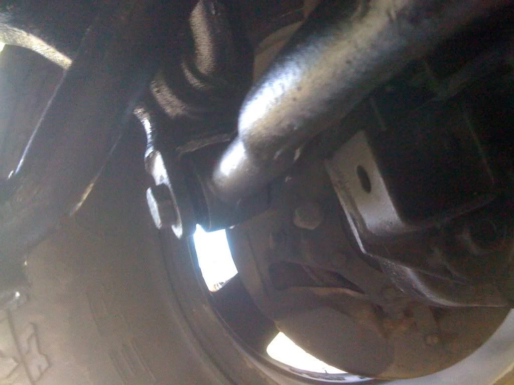
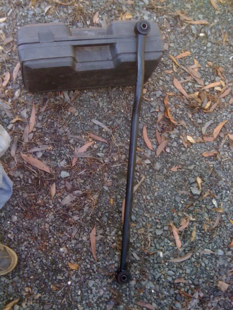
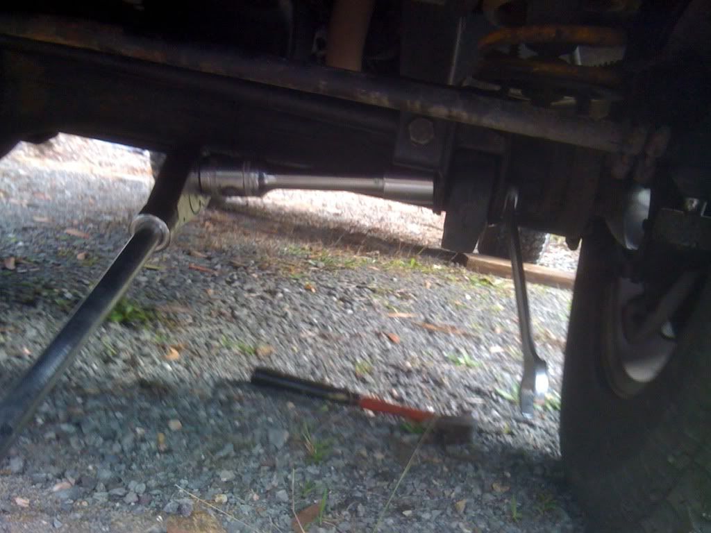
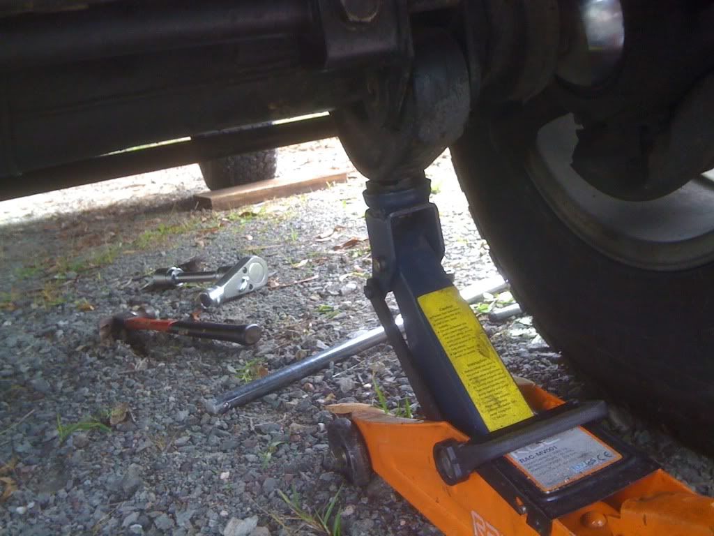
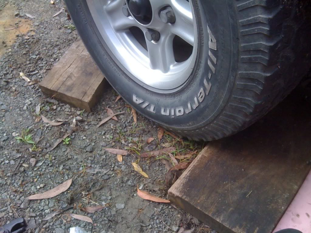
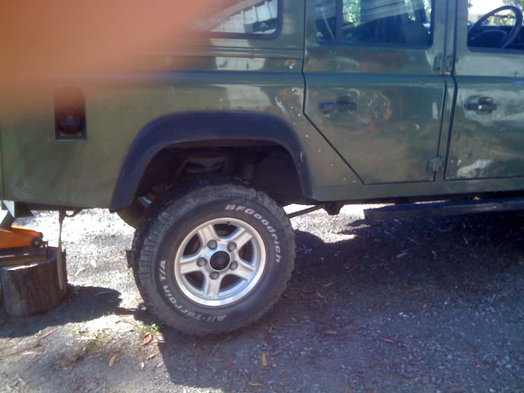
Then lets get to work, first of all we need to raise the vehicle so the axle is freely suspended in mid air, this will take the tension off of the A frame.


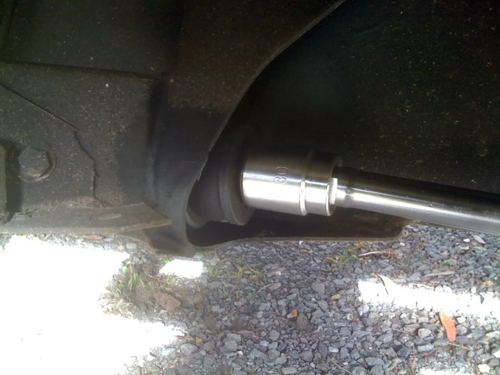
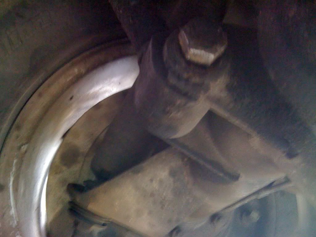
Then undo the bolts which attach the A frame to the chassis (30mm)


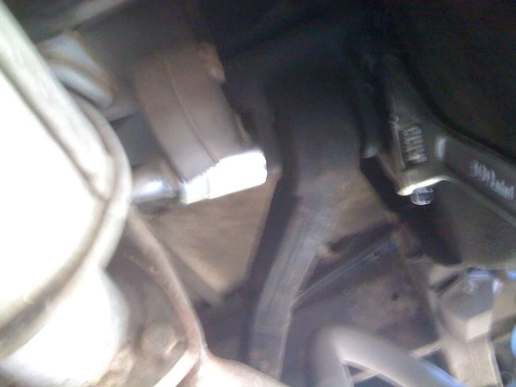
Do Not remove these bolts yet as we need to remove the ball joint attachment on top of the axle, this is attached by four 13mm bolts.


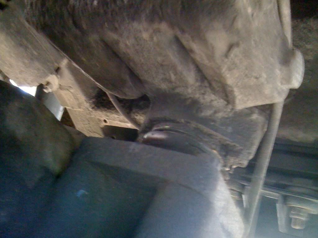
Once you have removed the four bolts on top of the axle, remove the bolts from the chassis attachment, at this point one of mine was seized in so I had to remove the chassis bracket consisting on three 17mm nuts and bolts.


Finally it was off and with the help of diesel and a big hammer as one of the bolts had become stuck, but after a few taps it popped out.
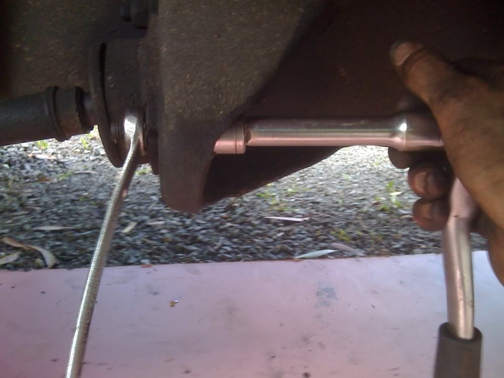
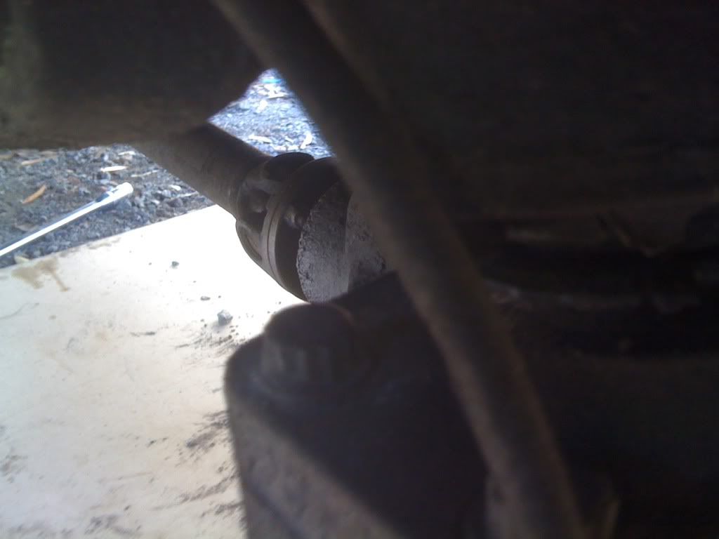
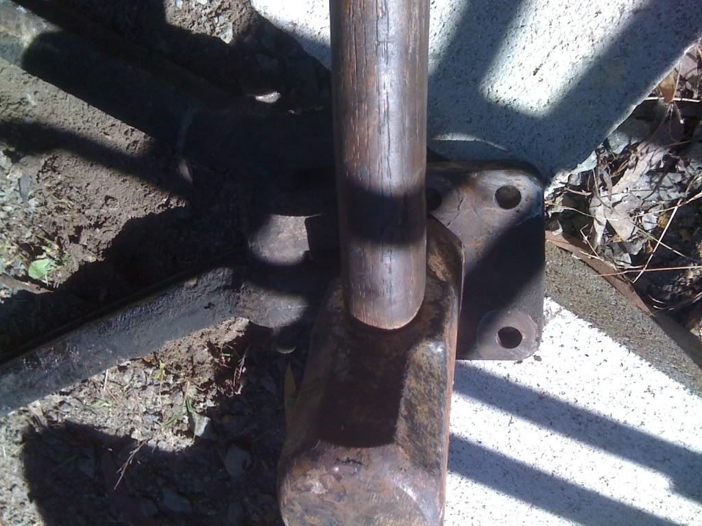
Now we have to remove the ball joint, I jammed a screw driver in the holes as I did not have a vice, and it was able to be undone.


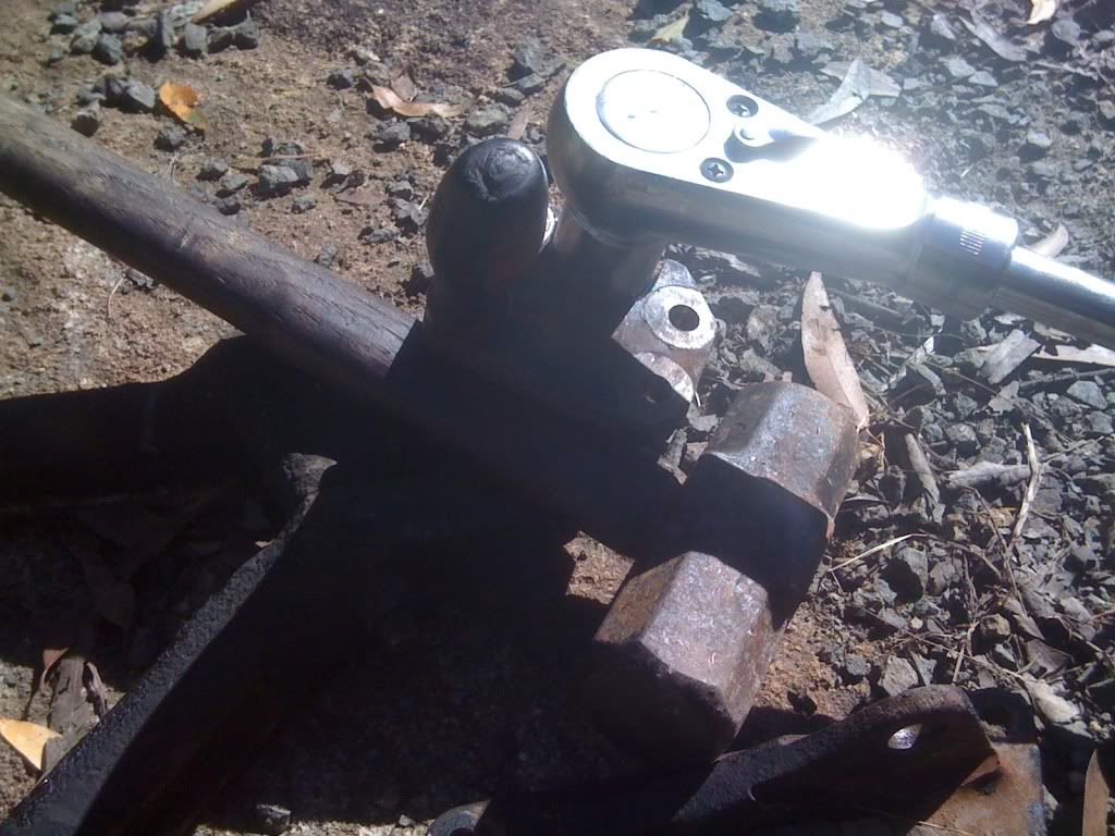
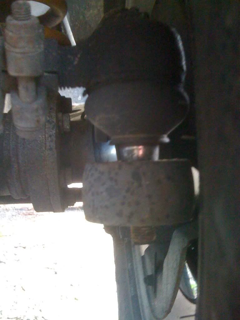
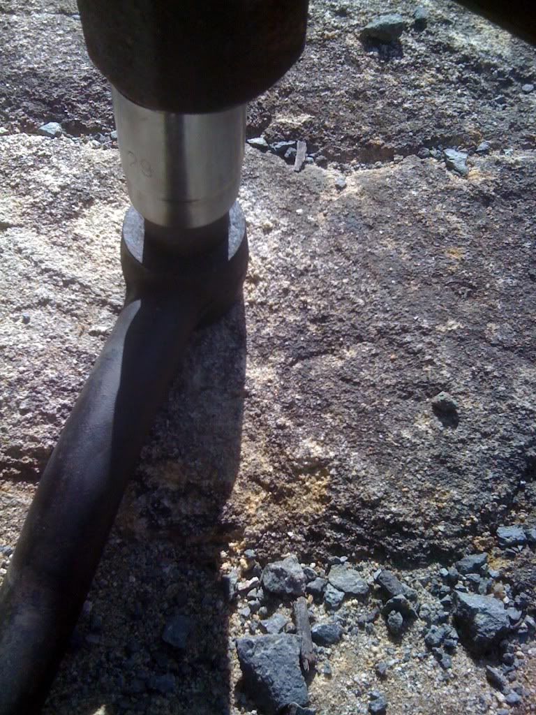
Now with the sledge hammer tap the nut end of the ball joint and it should become free of the bracket.


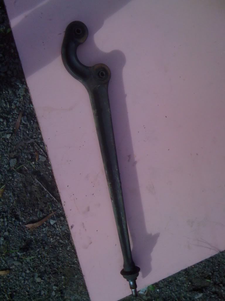
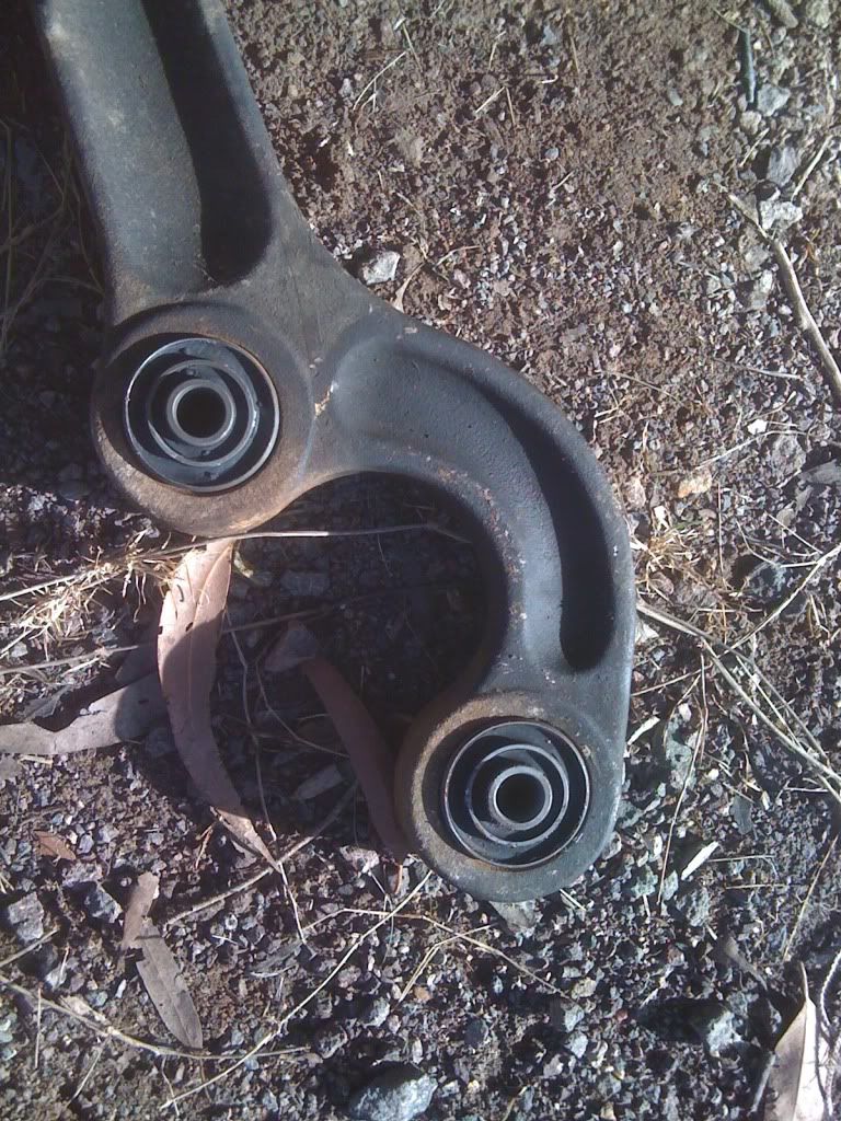
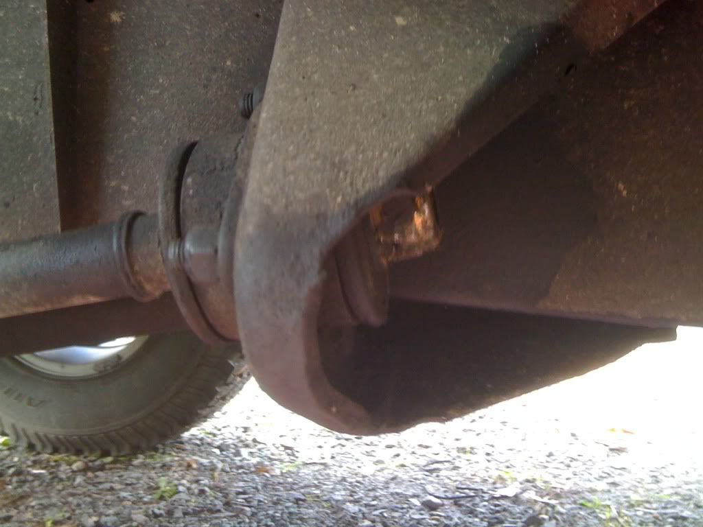
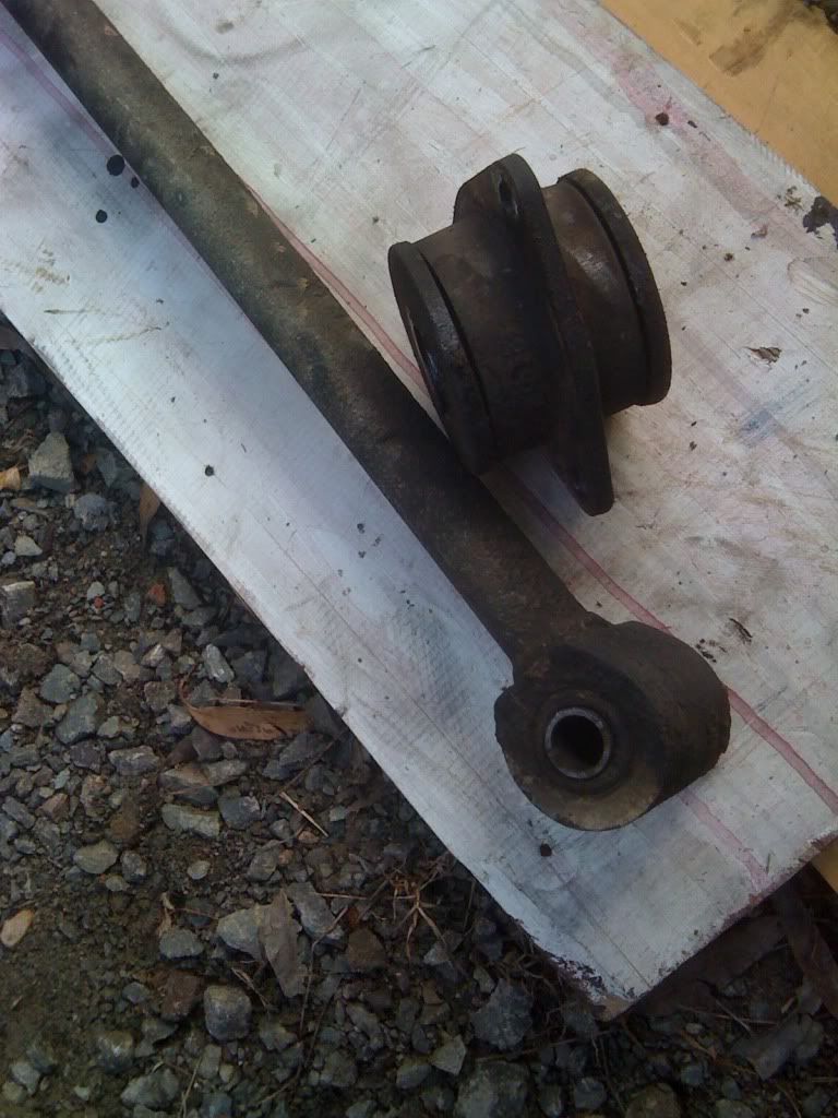
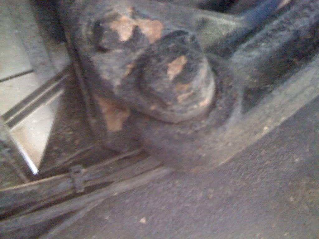
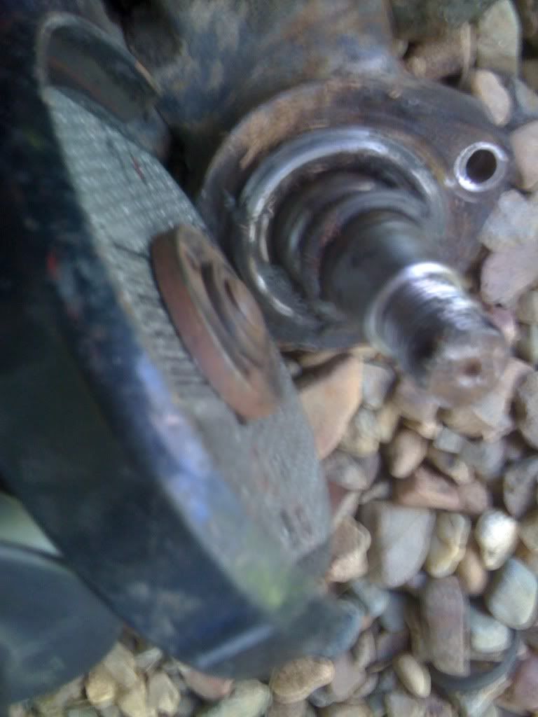
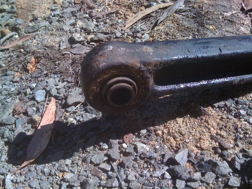
Now it free I could see how badly the ball joint was


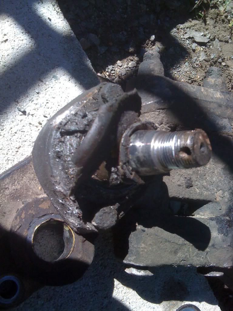
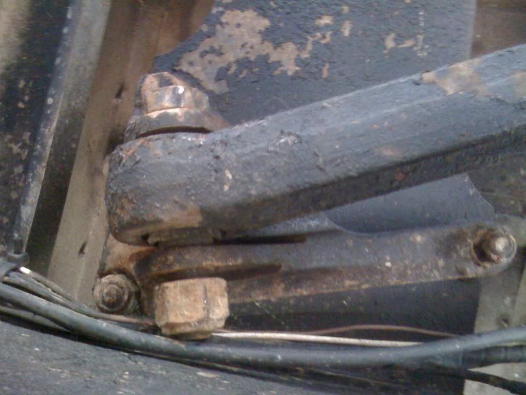
Now remove the two bolts either side of the ball joint, these were a 13mm.


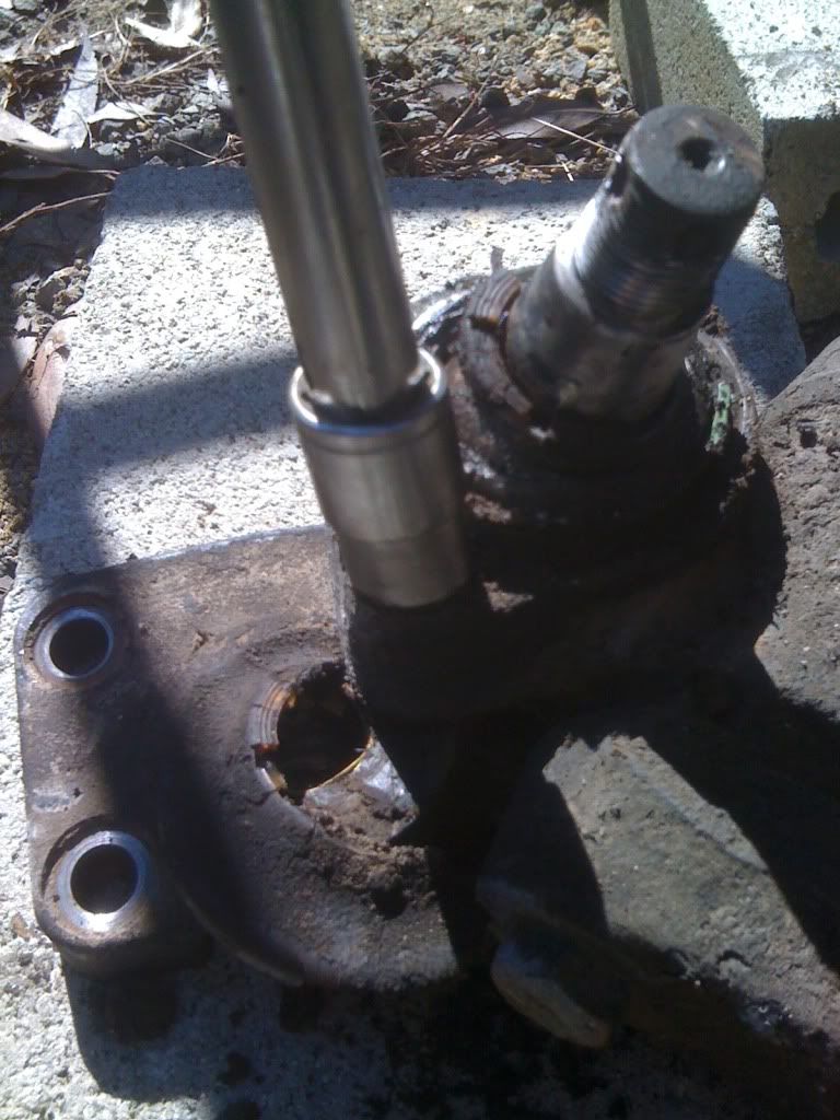
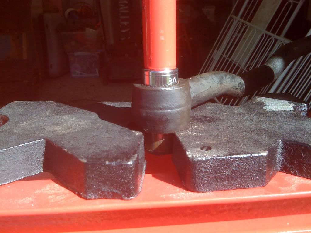
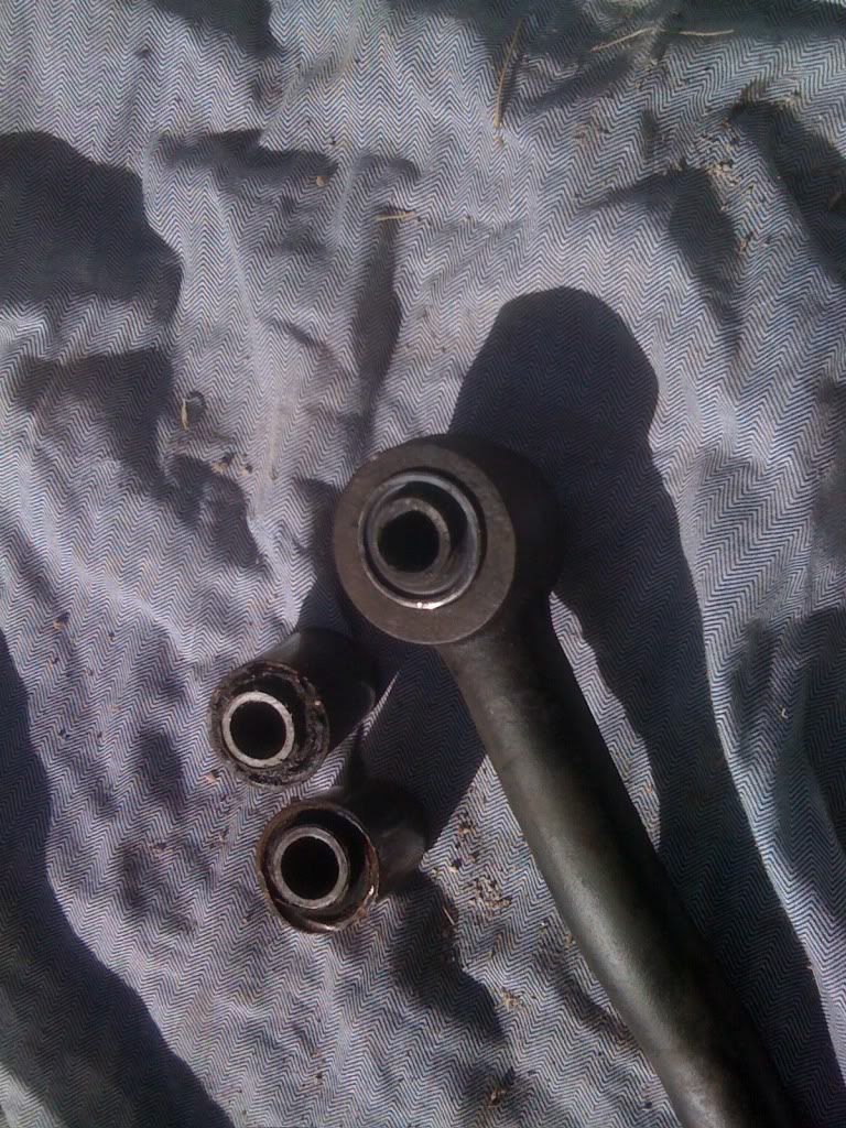
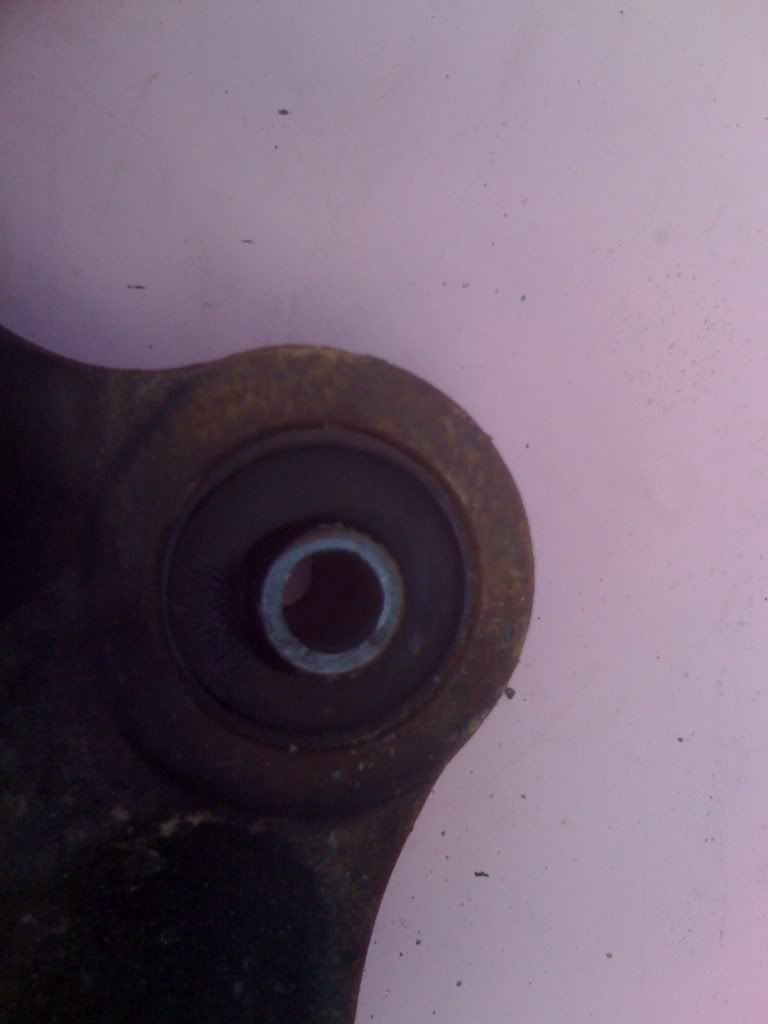
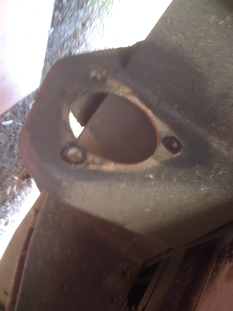
One the bolts were removed I had to cut with a grinder the flanges of the ball joint so the press could be used to press it out.


Once cut it should look like this


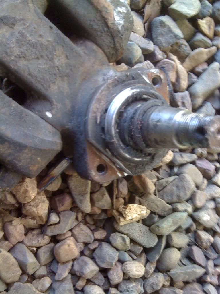
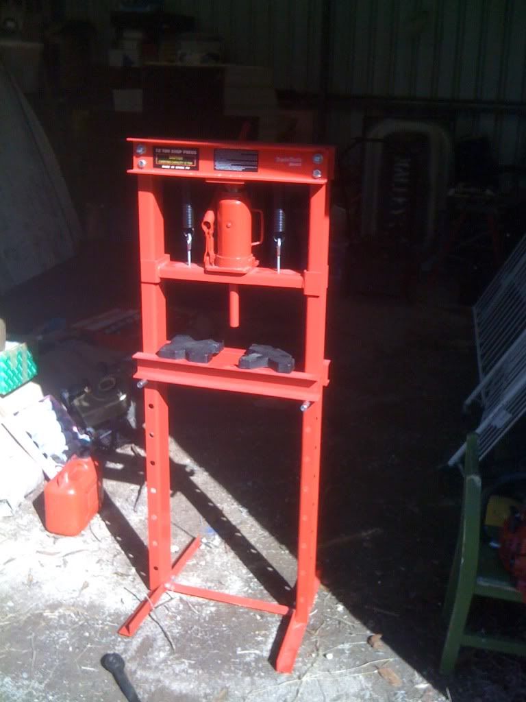
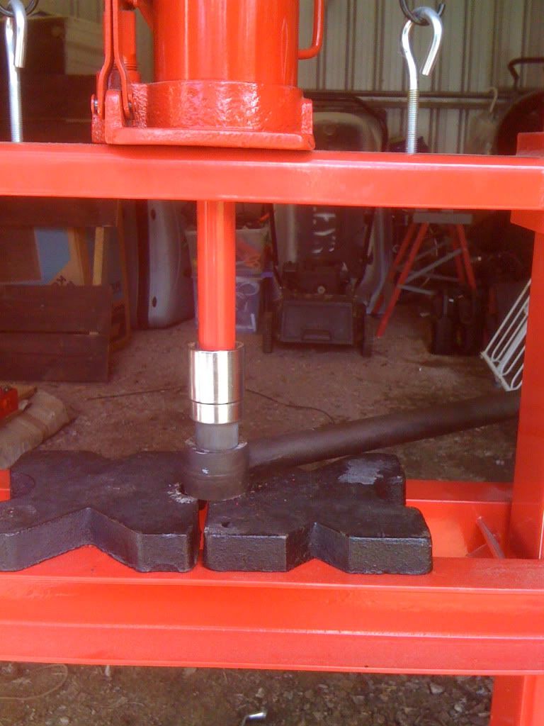
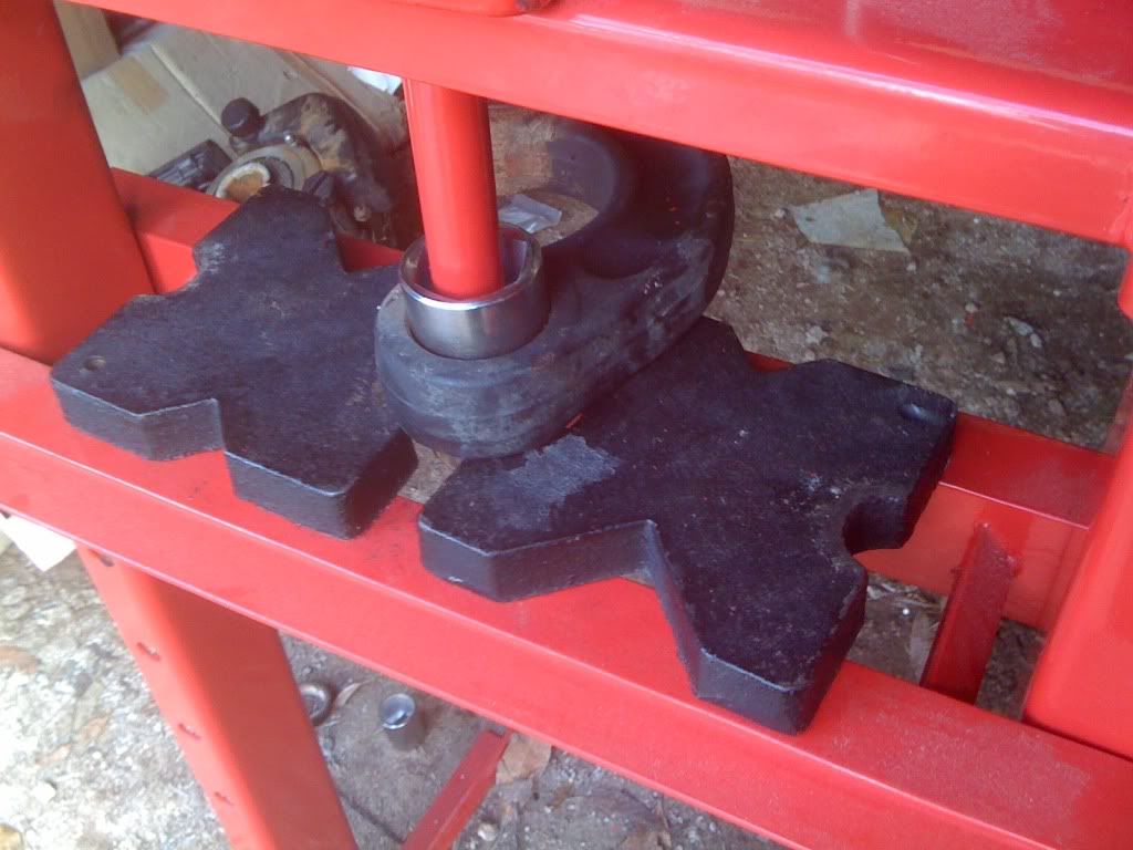
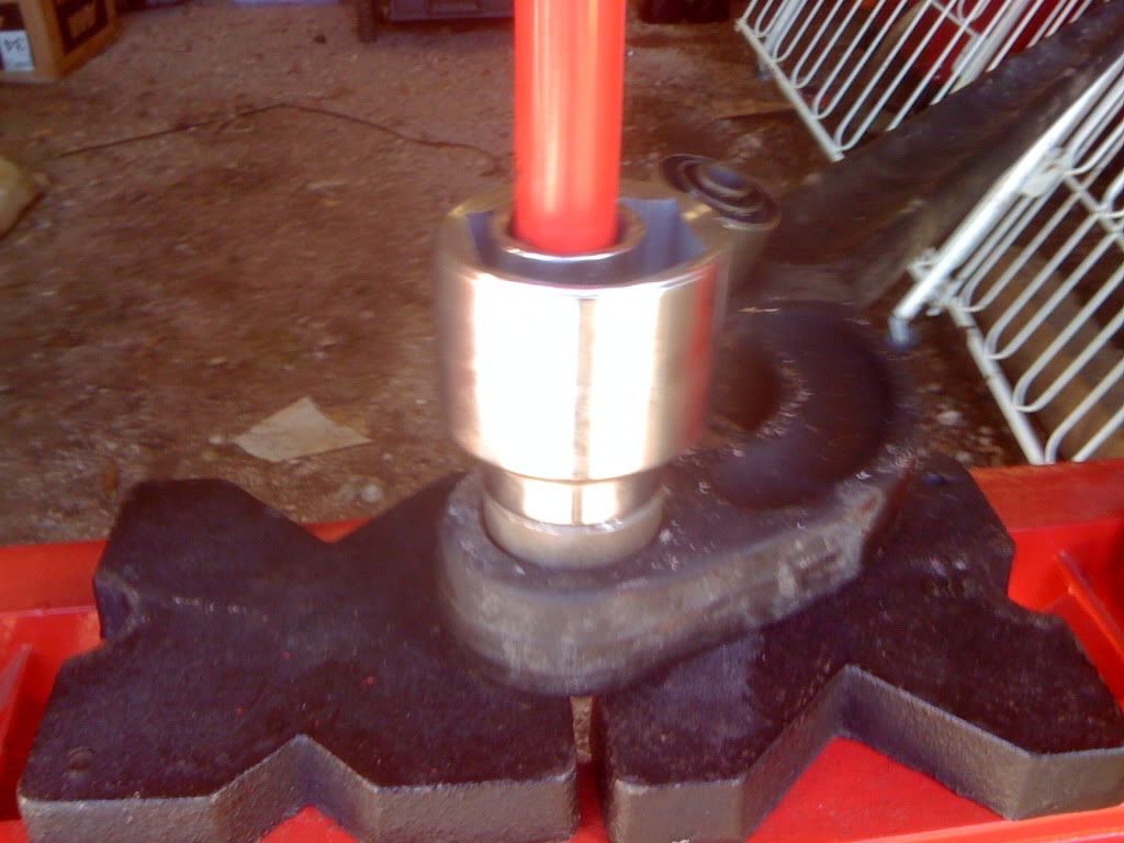
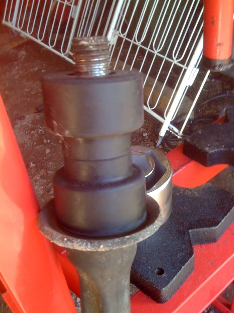
So it would not put too much stress on the press, I hit the ball joint with the hammer to loosen the rust around it. Then I put it in the press and pressed it out.
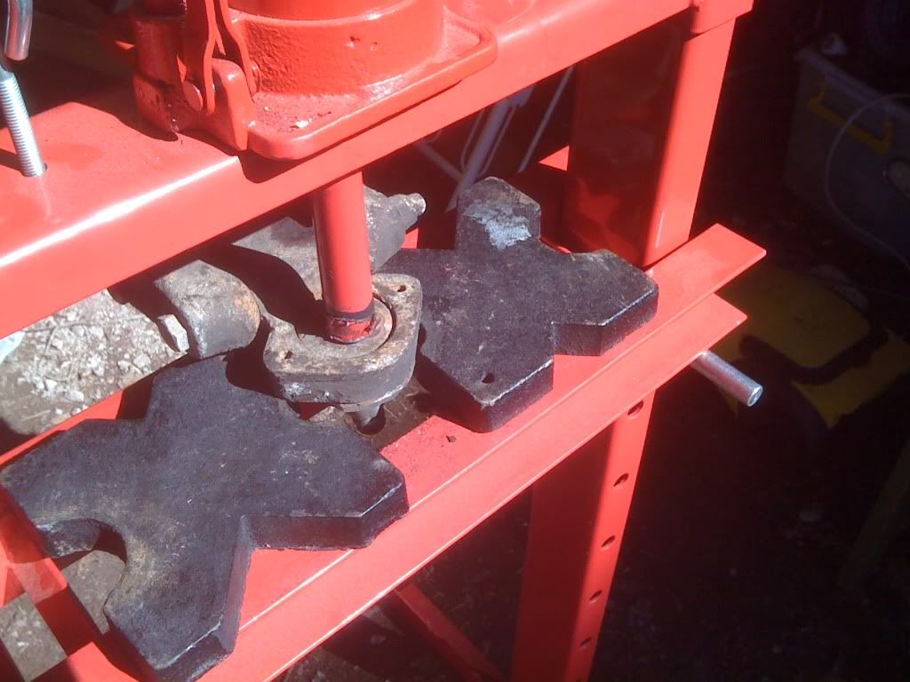

Once ou
t we need to put the new one back in.
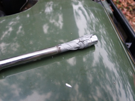
Finding a large socket, a small amount of grease, and the sledge hammer tap the ball joint home ensuring the bolt holes line up.


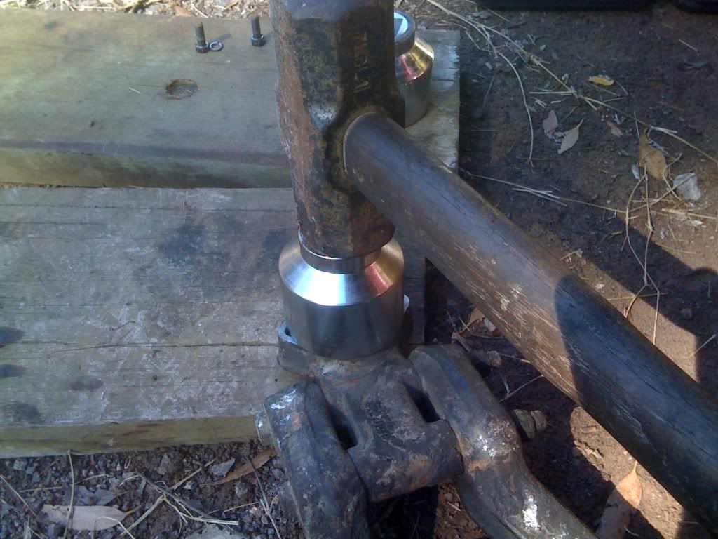
Make sure the ball joint is snuggly fit, and refit the bolts with some thread lock.


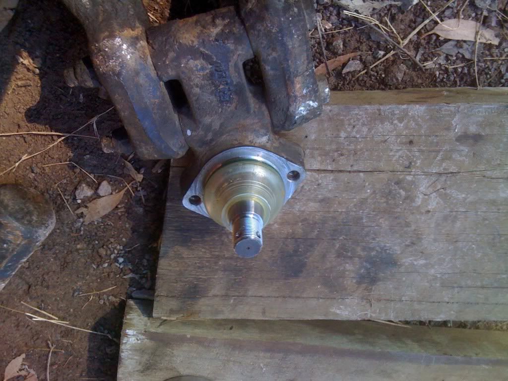
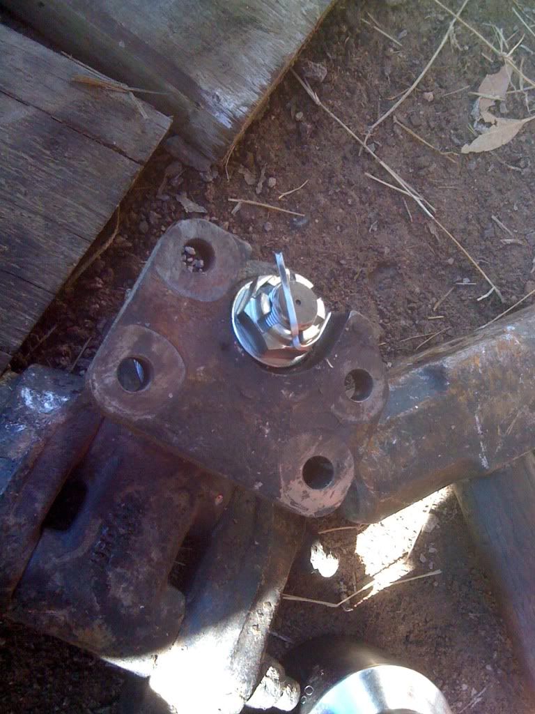
Place the axle bracket back on and tighten the nut and then put the split pin in.


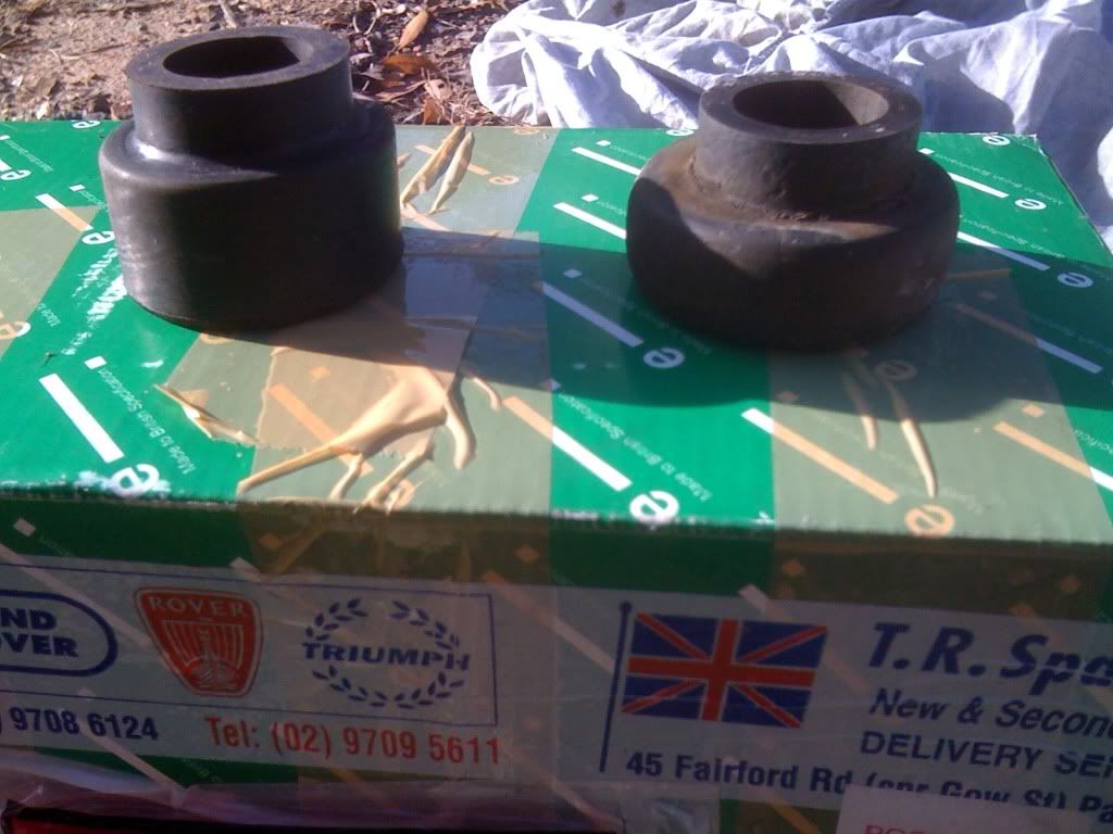
Press the A frame bushes as described in the previous section


Once the new bushes have been replaced put the frame in reverse order and you may need to just tilt the axle slightly to fit the top bolts into the ball joint bracket. Remembering to put stub lock on these too.

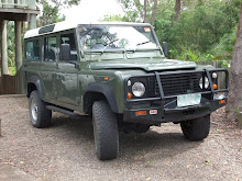
I hope this has helped as my Defender no longer clonks when the drive is taken up and the whole vehicle drives smoother.
Cheers Mark

Replacing the suspension bushes

Monday, May 23, 2011


Replacing the suspension bushes on a 1993 200 TDI 110


Land Rover 200tdi Suspension Bushes replacement
The ride was rough and the steering was wonder, it could not wait any longer!
This Bush kit cost $95-00 which included the anti roll bar kit, I don’t have one and the shock rubber kit. In total with postage it was $117-00. Not badly prices I thought.


Check the kit to ensure you have the right part numbers for your vehicle


Gather your tools together; I had a large drive socket set, a trolley jack, a 24mm spanner, a 19mm spanner, pliers, ball joint remover, 12 tonne bench press, a screw driver, 17mm spanner and the set of bushes.
Some wooden blocks or wheel chocks.


Chock the font and rear wheels after parking it on a flat surface, started with the Panhard rod, this consisted of two bushes and two bolts however I had to remove the drag link to give me access to one of the retaining bolts on the axle.


Remove the ball joint with the ball joint removing tools and mine was a 17mm for the nut and 19mm for the tool.


Once you have removed the Panhard Rod find a socket that fits the outer metal ring of the bush, not too big as we need it to go through the surround.


Slowly press the bush ensuring the press is pushing it square.


Once the bushes are pressed out place the new bush in, and I tapped it in a bit with another socket to ensure the press would press it squarely.


Press the bush fully home


An image of the old ones out and the new ones in, they had definitely gone.


Rebolt on the Panhard rod and place the drag link back on, torque up to required torque settings. Panhard bolts should be as stated in the manual 88Nm (65 ibf/ft)

Now the front radius arms.

I did this with the wheels on, but off would have been easier.
Remove the tie rod.

Remove the large nut where it attaches to the chassis. This was a 30mm nut.


Then using the large socket set remove the radius arm to axle bolts. These were 24mm


I had to use the screw driver just to pry the arm down.


Once the axle end is dropped it should just pull out.


Remove the bushes as previously stated using the press and replace with the new ones as previously done.

This one has also had it, no wonder the steering and cornering wasn’t fab!


Push the bushes home.


The new ones are looking good!


Comparing the old radius arm to chassis bushes!


Now place the first radius arm to chassis bush on and then put through the hole then align with the eyes on the axle and use a jack to put them into place do not tighten anything at this stage.


I had a slight issue, the new axle to radius arm bushes were slightly wider by 5 mm either side, so I had to grind them down, doing it in stages without causing the bush to over heat and damage the new bushes.

If it doesn’t fit don’t force it as you could damage the steel tubes of the bushes.

Once in place and the bolts are to be tightened to as the manual states. Don’t tighten until you have done both sides.

Radius arm to chassis nuts 176 Nm (130 lbf/ft)
Radius arm to axle bolts 197 NM (145 lbf/ft)

Once done replace the tie rod and tighten the ball joint nuts.
Now the rear axle

Ensure you securely block the rear axle to prevent the rear axle moving back too far when you remove the lower suspension link.


Loosen the large chassis to lower link nut, this was also a 30mm


Then loosen the axle to lower suspension link bolt. (24mm)


Ensure the wheel is securely chocked as the rear axle will move backwards slightly when you undo the large chassis nut.

Loosen the three nuts around the chassis link rubber bush. (15mm)


Remove all of the nuts and bolts and the arm should drop out.


Remove the chassis bush.


Once out, as previously press the old bush out, I found these bushes in the lower link harder that the front as the outer metal appeared to be thinner than the front.

Once in do not bolt the chassis rubber bush in as this will prevent you getting the lower link back in. Once the link is in,

the axle bolt should be tightened to 176 Nm (165 lbf/ft) and with the weight of the vehicle, the chassis nut should be 176 Nm (165 lbf/ft)

Since this has been done the vehicle corners and doesn’t wonder like it did. The next task will be the A frame suspension link and ball joint and the shock absorber rubbers.

I hope this helps,

Cheers Mark

Replacing the Heater Matrix on the Defender

Sunday, September 5, 2010

Hi all well my heater Matrix split on top and I searched on the net, prices ranged from $285-00 to $80-00 including shipping from the UK. DLS UK gave the best deal, and as I have purchased parts from them before, so 10 days after I had ordered the part it arrived.


The first thing was to get all of my tools together


you require:-


10mm socket

9 inch 1/4 drive extention

1/4 ratchet

Screw drivers

7mm spanner

pointed nose pliers

10 mm spanners

13mm spanner

torch (Very handy)


Remove the split pin on the bonnet stay and lift the bonnet fully open, tie it up to be safe.


Now remove the water washer bottle held in by 2 10mm nuts and then remove the frame which retains the bottle to the wing.


Once this has been done we can have better access to the heater box.


Remove the panel from the under dash aircon unit, this consisted of two 10mm bolts and 4 screws, 3 in the floor and one on the bulkhead bracket


Use the 7mm spanner and the pointed nose pliers to remove the cables and clips.


The grill covering the blower inlet on the top of the left wing, remove the screws and remove the grill, then there are 2 cross headed screws retaining the first stage of the air blower intake.


Remove the piping to allow movement of the blower part when we come to remove it.


When I took mine out the water drainage valve was blocked and had caused the fan motor to flood and swim in water


the swimming motor


once removed we can now remove the water pipes and start removing the retaing bolts.


I then placed a spanner on the lower two nuts from within the engine bay on the heater box jamming it against the box, and taped a 10mm socket and with using a torch aligned the socket onto thebolt and started to undo them, they came out really easily.


the lower nuts


Once out then there are two nuts on the upper part of the heater box, behind the heater matrix.


These are both 13mm and came out easily. the next thing was to disconnect the wire to the blower box.


The next thing is to wiggle the unit with the fan until your are able to remove it from the engine bay. I hade to slightly bend an Aircon pipe.


The next thing to do is top strip the unit down. The Matrix is retained by screws and brackets at the top and bottom.


remove the lower bracket which is held on by 3 10mm nuts


Once removed remove all of the screws holding the matrix retaing brackets and remove plates. Here is the bottom.


Pull the matrix from the heater box


Then here we check that the new part is correct


Due to my motor had been flooded I removed it to let it dry and cleaned the box and motor housing and put a fresh coat of paint on it.


The New Matrix did not come with the rubber pads on the bottom, so I removed them from the old matrix and glued them on.


Then slide the matrix back into the heater box and refit the retaining plates on the top and bottom.


Fit the lower bracket


Check the Bulkhead for rust and treat


Wiggle the heater box back into place and first of all. align the lower bracket holes and with the taped socket, push the bolts from the inside using the torch, and the light coming from the engine bay, then pack into position and go to the engine bay, place the nuts and washers on and then jam the spanner again and tighten with the ratchet.


Once these are tight refit the upper bolts making sure you don't jam the wire inbetween the heater box and the bulkhead.


Re connect the cables ensuring they operate correctly.


Once fitted join the wiring connector and then fill the heater matrix using the water hose and a can until it is full, this will prevent an air lock.


Once full connect the hoses.


Refit the under wing pipe ensuring the small valve is clear of gunk.


[


refit the screws and fit the wing grill. then refit the water washer bottle bracket and then the water bottle. Then refit the air con cover in the passenger footwell.


Stand back and check your work